This is SainSmart ramps 1.4 2-in-1 development board for 3D Printer, I am one of an engineer on ebay seller trade_spotting. Now I just introduce the motherboard of SainSmart ramps 2 in 1. If you have any questions or need the discount of the fixed price of eBay ., you can contact me as well. My skype id is ” jack.jun1 ”. I am not the CS, so My pronounce may be informally. I beg your pardon. Please note that, no matter what the problem you have, please contact us first. A part of customers, who are starter of 3D printer, lodge complaints without any communication. It is temerarious and irrational. As is known to all, 3D print is a new field, we could not accomplish at one stroke. Before leaving our factory, each Board or kits of sets are tested to ensure top working performance. But the transportation is unexpected.
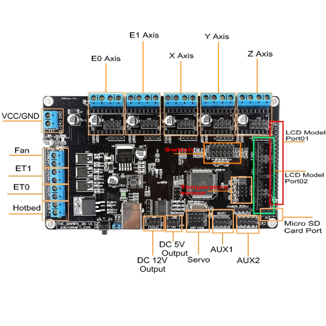

1: Power Supply (GND/VCC)
As is known to all, the old version ramps 1.4 is just compatible with 12V power supply, but now the new version ramps 2 in 1 board is compatible with 12V as well as 24V , we just need one channel power supply. We truly recommend you use 12V power supply and no less than 10A current. Your 3D printer machine may not work normally due to low power. Some of our customers do not know why their machine could not work and complain to us. If you machine could not work, please check it out of your power supply firstly.
2: Fan module port
Your extruder need to cooling.
3: extruder(ET1)
4: extruder(ET0)
5: Hotbed
You need a holder of your model
Note:
A: Please read the mark of the board, "+" means VCC, "-"means GND, do not confuse the connection.
B: The output of 2,3,4,5 is 12V, You should program on your computer and then they start to work. They could not work as you just provide the power. The voltage between VCC and GND is 12V output.
C: If your firmware are from the official, you should configure the hotbed sensor by yourself.The original firmware configuration of marlin below,

please note that What you configure the parameter is just depends on the style of your temperature sensor. If you don not program this part correctly, your atmel CPU will be damaged. Burned
If your thermistor is 100K ohm, Change the default configuration to
#define TEMP_SENSOR_0 1
#define TEMP_SENSOR_BED 1

6: Extension port
   DC 12V output

7: Extension port
   DC 5V output

8: Extension port
   Servos interface

9,10: AUX interface
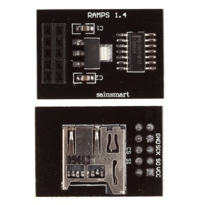
11: Not only the LCD model but also the SD card slot model are included in this part.
The picture below is the micro SD card module, If your card is micro SD card, you could use this module. Actually, the SD card slot has been integrated on your LCD Module. What you choose is just depended on ur SD card style.
 OK, well, I am not good at English, I do not know that whether you have got the point of my words. Let's go on,
If you use the micro SD card to store your data, you do not need the Converting Interface below, just plug your two Flexible Cables on EXP1 and EXP2.
OK, well, I am not good at English, I do not know that whether you have got the point of my words. Let's go on,
If you use the micro SD card to store your data, you do not need the Converting Interface below, just plug your two Flexible Cables on EXP1 and EXP2.
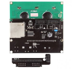
 But if you just want to plug your normal SD car on your LCD module, then the connection may be another way.
 Two flexible cables, please do not confused of the connection. The connection is the same as the ramps 1.4 board, look at the picture below

On the contrary, if you connect the cable on the other way, the LCD may not display normally.
You could contact us for help as you still have problem of the connection. The worst is that you have tried a lot of times but still can not light up the backlight of the LCD. contact us please. eBay message is sincerely recommended.

15: Switch interface
    mechanical or Opto Endstop switch, if you want to stop when the machine is printing, you may need the switch, nothing about to say on this part.

16: Z motor and driver interface
17: Y motor and driver interface
18: X motor and driver interface
19: E1 motor and driver interface
20: E0 motor and driver interface
Look at the driver module, do not connect the driver on the wrong direction, otherwise, you may ruin the driver. In order to make sure that all the motors could work perfectly, I sincerely suggest you to run the debug program.

Connection
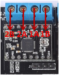
 If the motor you use is from our store, the wiring connection below
2B 2A 1A 1B
RED BLACK BLUE GREEN


